
The Flight Module computes the airplane Speed vector taking into account the four basic forces acting upon an airplane in flight - Thrust, Lift, Drag and Gravity. The Speed vector has both magnitude and direction.
The magnitude of the Speed vector can be generally expressed using miles per hour (MPH) or kilometers per hour (KPH). For unknown reasons, airplanes in the US generally use Knots per hour. For computation purposes, the magnitude is generally expressed in US units of feet per second (fps) or in SI units as meters per second (mps). The Flight module uses SI units for computations, which the programmer can convert to the desired units for display purposes.
The direction of the Speed vector can be defined in terms of the Vertical Angle relative to the horizon (the x-axis) and the Horizontal Angle relative to true North (the y-axis). The Vertical Angle ranges from plus 90 degrees (straight up) to minus 90 degrees (straight down). The Horizontal Angle ranges from 0 to 360 degrees, starting with 0 degrees (true North) and proceeding in a clockwise direction.
Thrust and Drag change the magnitude of the Speed vector. Lift changes the direction of the Speed vector. Gravity can change both, depending on the Vertical Angle of the Speed vector. In level flight, Gravity only deflects the Speed vector downwards. In vertical flight, Gravity only changes the magnitude of the Speed vector. In between these extremes, Gravity does both. In mathematical terms: the amount of deflection equals Gravity X SIN(Vertical Angle); and the change in magnitude equals Gravity X COS(Vertical Angle).
There are two sets of Reference Planes: the Global Reference Planes and the Airplane Reference Planes. The Global Reference Planes are the Vertical and the Horizontal Planes, discussed above. The Airplane Reference Planes are the Pitch (x-axis), Bank (z-axis) and Yaw Planes (y-axis).
Of these, the three primary reference Planes are the Pitch Plane and the Vertical and Horizontal Planes. Changes along the Airplane Bank Plane do not directly affect the Speed vector magnitude or direction. Changes along the Airplane Yaw Plane are rarely made.
Lift deflects the Speed vector along the Pitch Plane, which result in changes along the Vertical and Horizontal Planes. Gravity deflects the Speed vector along the Vertical Plane. Together, Lift and Gravity can generate changes along the Horizontal Plane (which is how an airplane turns).
Figure 1 shows these three primary Reference Planes and how changes in airplane Pitch, Bank and Yaw result in changes to the direction of the Speed vector along the Vertical and Horizontal planes. For now, the impact of Gravity is ignored.
An Airplane has three basic directional flight control surfaces which cause rotation along the Pitch, Bank and Yaw Planes (the x, z and y axes). These are:
- Elevator - the horizontal control surface at the tail which causes the nose of the airplane to pitch up and down, which increases or decreases Lift.
- Ailerons - the control surfaces on the wings which cause the airplane to roll left and right.
- Rudder - the vertical control surface at the tail which causes the airplane to yaw left and right.
Example 2 shows the operation of the elevator (up/down arrow keys), ailerons (left/right arrow keys) and rudder (z/x keys). This example also shows how, in a banked turn, Lift and Gravity cause the airplane to rotate horizontally.
In Vertical Flight, the two primary forces are Lift and Gravity. Lift is primarily a function of Speed and Angle of Attack (AoA). Roughly speaking, AoA is the difference between the direction the airplane is pointed and the direction of the Speed vector along the Pitch Plane. The greater the AoA, the more Lift is produced up to a maximum of around 16 degrees, plus or minus (see discussion of AoA below). An increase in AoA also causes an increase in Induced Drag, which reduces the airplane Speed.
Example 3 shows how the Lift and Gravity deflectors affect an airplane in non-turning flight. In level or fixed-angle climbing flight, the Lift and Gravity deflection vectors exactly offset each other. As noted above, as the Pitch Angle increases, the amount of Lift required to offset Gravity decreases, since more of the Gravity acts to decrease airplane Speed.
In level non-turning flight, the Lift and Gravity Forces are equal. When the airplane is banked, some of the Lift is deflected horizontally. In order to remain in level flight, Lift must be increased so that vertical Lift equals Gravity. The additional horizontal Lift causes the airplane to rotate horizontally. The greater the Bank Angle, the greater the Lift required and the greater the Turn Rate.
The formula for the rate of turn (deg/sec) = TAN(Bank Angle) X Speed(mps) / Gravity(mps2). As this indicates, the rate of turn varies positively with Bank Angle and negatively with Speed. The greater the Bank Angle, the greater the Turn Rate. The greater the Speed, the lower the Turn Rate.
The Bank Angle is limited by the amount of Lift that can be produced at various Speeds. As Speed and Lift increase, the Minimum Bank Angle Increases. At higher speeds, the Bank Angle is also limited by maximum AoA (which limits Lift) and, later, by G-Force limitations. Flying at maximum Lift and maximum AoA will also create a lot of Induced Drag, which will tend to slow the airplane.
Thus, if a typical airplane which is at flying straight and level at Maximum Speed, attempts to make a maximum rate level turn, the Bank Angle will initially be limited by G-Forces (discussed below). The increase in Induced Drag will cause the airplane to slow down, which will result in a decrease in Lift and maximum Bank Angle. At the same time, this decrease in Speed also results in an increase in Turn Rate. The Turn Rate performance of an airplane at different speeds and Bank Angles can be illustrated by an E-M Diagram (discussed below).
Example 4 shows the interplay between Airspeed, Bank Angle, and Turn Rate.
And finally ... here is a Free-Flight Demo ( WebGL2 version or WebGPU version). You can fly the airplane manually, using a mouse or mousepad. Or you engage the Autopilot and adjust Pitch and Bank using the arrow keys. You can also select an internal view which has operating gauges animated using three.js.
The Angle of Attack (AoA) is also a key component of both Lift and Drag. AoA is defined as the difference between the direction of the Airplane Wing chord and the relative wind. In rough terms, this is the same as the difference between the direction the airplane is pointed and the direction of the Speed vector along the Pitch Plane. For most airplanes, the AoA can range from roughly -16 to +16 degrees. Beyond that range, the wing will "stall" and no longer produce Lift.
Since airplanes require a positive AoA to fly, most airplane designers tilt the wings back to produce an AoA equal to the AoA required for cruise flight. However, this is not necessarily done for aerobatic airplanes since they are also designed to fly upside down.
In real life, the pilot changes the airplane direction, which changes the AoA, which changes the Coefficient of Lift (CfL). However, this vastly complicates the design of flight simulations because the simulation must keep track of both the airplane direction and the direction of the Speed vector. Keeping the two correctly aligned can be quite challenging, especially in certain flight regimes (e.g. steep banks). The Flight module simplifies this process by assuming that the pilot is directly changing the direction of the Speed vector, including the CfL. This is mathematically valid because there is a linear relationship between AoA and the Coefficient of Lift (AoA = CfL/10).
Thus, the Flight Module can simply treat AoA as a by-product of pilot induced changes to the Coefficient of Lift.
The E-M Diagram shows the maximum Turn Rate for an airplane at different Speeds.
This is a valuable tool for measuring the performance of an airplane in Air Combat.
Here is a sample E-M Diagram for a WWII airplane:
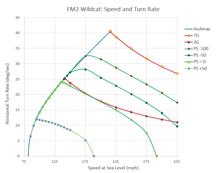
The blue line on the left shows the Maximum Turn Rate as Speed increases. The red lines show the Maximum Turn Rate allowed by G-Force limitations. Although the G-Force limitation on a WWII aircraft is relatively low, most do not have the Thrust necessary to keep the airplane at the G-Force limit at all Speeds. Thus, the turn rate will generally be less than the G-Force limit for most of the performance envelope. The green PS lines show how Gravity can be used to increase Turn Rate, with PS=0 representing a level turn. Of course, the disadvantage of using Gravity is that you also lose altitude. One shortcoming is that these Diagrams do not show the Turn Rate you can achieve with a Vertical Loop, which can be quite significant.
Because the Speed vector is rotating around a central axis, you can compute the deflection angle by converting the Deflection Force to Acceleration and using the formula: Deflection Angle (deg/sec) = (Deflection Acceleration (mps)/ Speed (mps)) * (180/PI). As shown, the deflection angle is affected negatively by Speed - the greater the Speed, the smaller the Deflection Angle. For example, in the case of an airplane in level flight at 300 MPH, Gravity will deflect the Speed vector downward by 4.186 degrees per second. In order to maintain level flight, Lift must be sufficient to deflect the Speed vector upwards by the same amount - in this case by 4.186 degrees per second.
In level non-turning flight, Gravity deflects the Speed vector downward. Thus, the Lift required to keep the airplane in level non-turning flight is equals 1X the Force of Gravity (1G). Where the airplane Bank Angle is 60 degrees, the amount of Lift required to keep the aircraft in level flight is 2G. A WWII airplane could generally withstand a maximum of around 6Gs. Since Lift is greater at higher airspeeds, it is easy to see how the risk of overstressing the airplane is greatest at higher Speeds. To compute the G-Force created by Lift, simply divide the Lift Deflection Angle by the Gravity Deflection Angle at that Speed.